Canon’s EF-M Mount’s Lens Type Detection
In this Long Discussion on Canon’s Rumored Mirrorless Mounts I discussed the idea of handshaking and negotiating different protocols and speeds for a bus used to communicate with a lens. Further along in that article, I looked at Canon’s EF-M mount standard and how Canon was already doing a type detection with EF-M lenses. I wrote a bit, but didn’t do a very through analysis of the type detection process.
So in this article I’m going to look in more depth at the type detection used in the EF-M mount.
Also, I should probably point out, I’m not an engineer for Canon or any other electronics company. I do have a bachelors degree in Computer Engineering though, but it’s been quite a while since I’ve done much on the electronics end.
Details in this article are taken primarily from Canon’s patent filing on the EF -M mount, this is US Patent No. 9,638,987 B2 issued on May 2, 2017 (filed Apr 4, 2013).
Background
Though not the first to market with an autofocus camera system, Canon did lead the industry in moving to a fully electronic lens mount. In doing this Canon set the stage for potentially seamless transitions to any future mount they might need. Moreover, this capability has been exploited by many others in the industry to bring EF mount lenses to other platforms, such as Sony’s E mount, Micro Four Thirds (u4/3), and to non-Canon cameras like Red and Blackmagic Design cinema cameras.
In 2004 Canon extended the EF mount with the EF-S mount. Designed specifically for crop cameras, the EF-S mount exploited space freed up by the smaller mirror to shorten the minimum back focus distance.
Mechanically the EF-S mount is backward compatible with the EF mount; EF lenses can be mounted to EF-S cameras, but EF-S lenses cannot be mounted to EF cameras. Electrically, the EF and EF-S lenses are, so far as I can tell, identical.
For simplicity the rest of this document will simply use EF to denote EF and EF-S lenses.
In 2012 Canon introduced their first completely new still camera mount since EF, the EF-M mount. The EF-M mount was designed for their EOS M mirrorless camera platform. While it definitely traces it’s lineage to the EF mount, the EF-M mount is not directly physically compatible. Due to the shorter flange focal distance used in the EF-M mount, a completely passive “spacer” mount adapter must be used to connect EF lenses to EF-M cameras.
As a product of their time, the EF, and by extension EF-S, lenses use 5.5 V for logic and signalling.
In the quarter century between release of the EF mount, and the release of the EF-M mount, the electronics landscape has changed considerably. Principally modern electronics operate at higher clock frequencies and lower voltages.
With the EF-M mount, Canon elected to change both the voltage and signal rates used in camera/lens communication to a lower (estimated 2.5 V) standard and simultaneously increase the signaling clock rate.
These design changes poses a problem in detecting the type of lens attached and selecting the right voltages and signalling for it. A mechanism is needed to determine the type of lens attached to the EF-M mount in order to provide the right signaling.
Conventions
In this document, I’ll be talking about pins, circuits, and the like, which in many cases have similar or identical names. To differentiate things, I’ll be using the following convention.
- NAME (e.g., DTEF, or MIF) – The name of the circuit in question. For example, “the DTEF circuit is used to detect the type of lens connected to the camera.”
NAME(e.g.,DTEF,VREF) – This is the name of a pin, connection, input or node in a circuit. It’s wrapped in code tags to separate it from being a descriptive name. For example, “V3is the reference voltage used by the MCU.”
Electrical Changes in EF-M
With the EF-M mount, Canon introduced two new pins: MIF and DTEF.
MIF replaced the microswitch used in Canon EF mounts that tells the camera that the lens is fully mounted and ready.
DTEF (probably short for DetecT EF), provides an electrical handshake for detecting, through the EF-EOS-M mount adapter, if an EF lens is used.
Otherwise, the remaining pins serve the same functions as they do on an EF mount lens, though the order of the pins has changed.
Device Detection / Handshaking / Negotiation
As noted earlier, EF-M lenses use a lower voltage and higher clock than EF lenses do. To build a system that can communication natively with both EF and EF-M lenses, some form of negotiation needs to take place.
Broadly speaking there are 3 ways to approach this problem.
First, you can do the protocol negotiation at the logical level. In this case, that would mean that the electronics in EF-M lenses would need to be 5V tolerant, and capable of operating at both EF and EF-M clock speeds.
Overall the process would work something like this:
- Mount complete state is detected (
MIFpin is pulled low) - Camera initiates communication with lens asking for it’s ID using EF clock rates and logical protocol
- Camera looks up lens ID and determines what voltage levels and logical protocol to use
- Camera changes link voltage and frequency (partial reinitialization)
This is somewhat similar to how USB devices, negotiate higher charging voltages and currents. However, there is also a significant difference in that USB’s normal voltage is 5V, and higher voltages have to be negotiated for by the device.
In this case, the “standard” voltage is 5 V, and a lower voltage would be negotiated. That would mean that EF-M lenses would have to use 5V tolerant electronics to not be damaged.
The second approach would be electrical at a lower level. In this case, you’d change the state of a pin, or pins, between logic-high (1) and logic-low (0) to code in the type of lens.
The final approach, and the one Canon chose to use, is a voltage based analog sense that encodes the type of lens.
Fundamental Considerations
One fundamental consideration of this kind of process is that the negotiation process should not harm the attached lens or camera; it should fail safe.
In the above case of USB, the standard voltage the USB bus is 5V. All USB devices must be able to operate at 5V. Since that’s where it starts, and higher voltages have to be requested, it passes the fail safe test.
However, Canon’s lenses have gone the other way. EF-M lenses, operate at a lower voltage than EF lenses.
Moreover, with any voltage/signalling negotiation mechanism, the engineers must consider a wide range of factors that might affect the devices operation and how to fail safely so as to not damage equipment.
For example, since lenses rotate into locked position, as the lens is rotated all but 1 contact crosses multiple other contacts. If a low voltage data pin were to be dragged across a energized 6V servo motor power pin, that connection could easily damage the low voltage electronics.
Incidentally, Canon accomplishes this in the EF-M mount be keeping the VBAT and VDD disabled until after the handshake is complete.
Likewise, in the case of negotiating the lens type, the mechanism must be designed so that accidental, and natural, problems should cause it to fail safe. E.g., a dirty contact, shouldn’t cause a low-voltage EF-M lens to appear as a high-voltage EF lens.
Lens Lockup and Initialization Overview
As outlined in Canon’s patent, lens lockup and initialization for the EF-M system is as follows.
MIFis pulled low by the lens when the lens is fully seatedDTEFis altered by the lens and is measured by the camera control unitCNT_V_OUTis asserted or left low by the camera control unit based on the value ofDTEFto switch the voltage shifters to the correct signaling levels.CNT_VDD_OUTis asserted to enable the logic voltage to be sent to the lensLCLKis generated by the camera control unit and logical communication can commence.
When a lens is not mounted, which the camera detects when the MIF pin is pulled low. All but the MIF and DTEF pins are de-energized during this process. Therefore no voltage is applies to VBAT or VDD.
After MIF is pulled low by the lens, the camera controller measures the voltage of DTEF and compares the resulting values to it’s internal lookup tables to determine if its an EF or EF-M lens.
If the lens is an EF mount lens, then the camera controller drives CNT_V_OUT high, which selects V1 (5 V) as communication voltage in the level shifter. After a brief pause the MCU then drives CNT_VDD_OUT high which enables the lens’s logic power (VDD). With power enabled, the camera controller then generates an EF comparable clock signal on it’s LCLK_OUT which is shifted by the voltage convert to the V1 voltage level and sent to the lens via the LCLK pin.
For EF-M lenses, a similar process occurs, but CNT_V_OUT is kept low. With CNT_V_OUT low, the level shifter selects V2 as the voltage reference for lens communication.
What isn’t expressly called out in Canon’s patent drawings is that VBAT appears to be kept disabled until after communication with the lens is established, presumably at the logical level. At least, I can’t find a signal on VBAT on the EF-M or EF-EOS-M mount adapters when a lens is not connection.
Detect EF (DTEF)
The DTEF signal is based on a voltage divider circuit split between the lens and camera. When no lens is connected to the camera, the DTEF pin is pulled high by the internal “pull up” resistor. When a lens is connected, the lens pulls the voltage down (either directly to ground or through another resistor) producing a variable voltage signal that can be read by the MCU’s ADC.
Patent figures 13 A and B from the EF-M patent show the overall design of the voltage dividers used by the DTEF circuit.
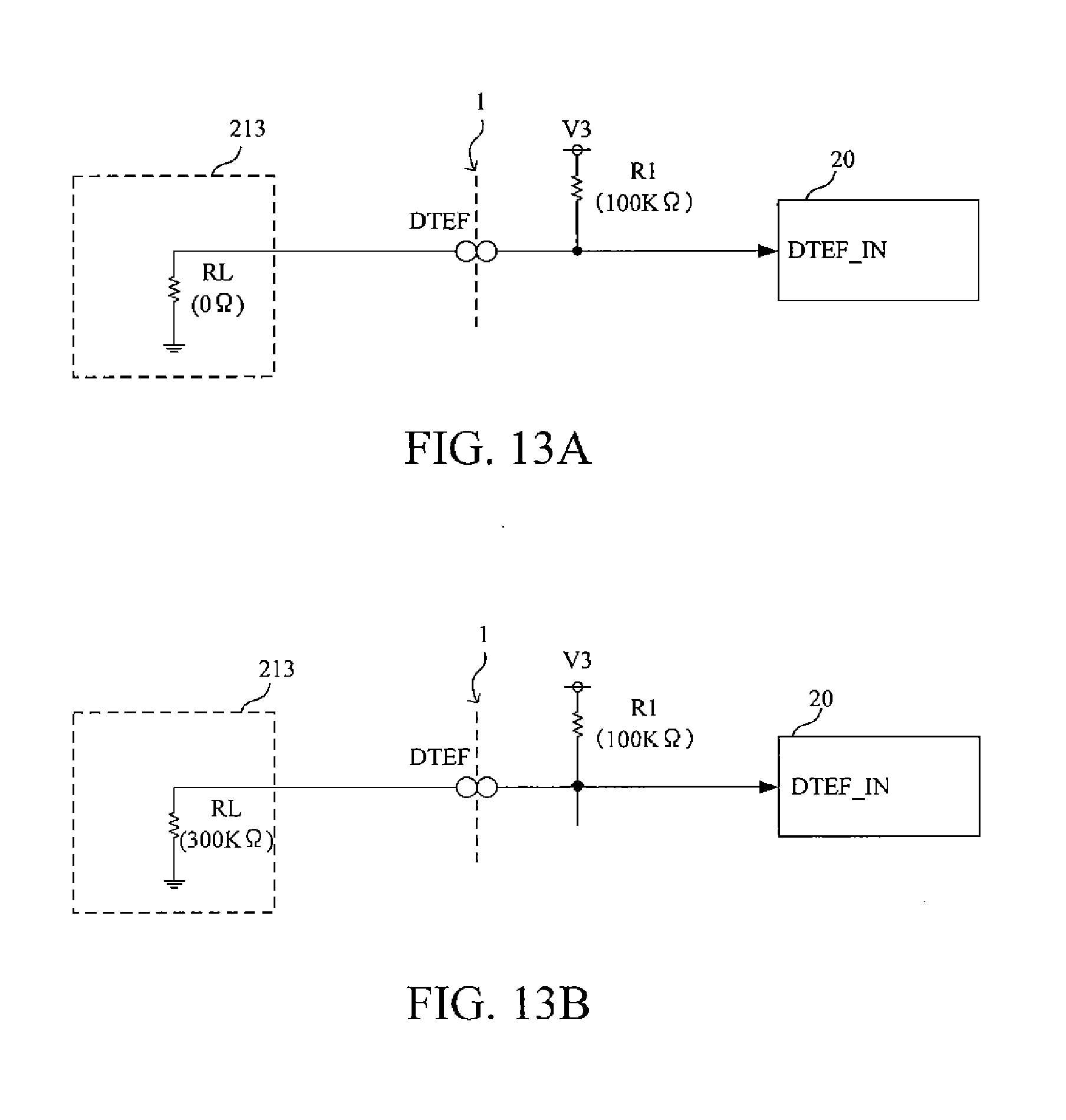
Voltage input is provided by camera’s V3 voltage plane. I’ve measured the voltage at the DTEF pin as 2.34 V, which likely means that the V3 plane is nominally around 2.5 V.
Internal to the camera is a resistor (R1), which Canon’s patents give as being 100 kΩ. The second resistor value is provided by the lens. In the case of EF lenses, there is no resistor, DTEF is connected directly to ground, so R2 would be 0 Ω. In the case of EF-M lenses, a second 300K Ω resistor is specified in the patent.
Given the two resistor values, the voltage divider when connected to an EF-M lens outputs at 3/4 of the reference voltage (V3).
The ADC DTEF_IN on the “camera micro-computer” or “camera controller” depending on the diagram (what I’m going to continue to denote as the MCU), is connected to the DTEF line between R1 and the pin on the lens mount.
The supported values for the DTEF ADC output are provided in the patent in Table 1 (reproduced below).
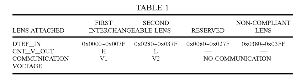
And the ranges reordered by the resulting digital value.
| EF | Reserved | EF-M | Non-Complaint |
|---|---|---|---|
| 0 – 127 | 128 – 639 | 640 – 895 | 896 – 1023 |
00 0000 0000 |
00 0001 0000 |
10 1000 0000 |
11 1000 0000 |
00 0000 1111 |
10 0111 1111 |
11 0111 1111 |
11 1111 1111 |
Based on the table, it appears that Canon is using a 10-bit ADC; 0x03FF is 0011 1111 1111 in binary, which is 10 bits all on. A 10-bit ADC creates 1024 values covering a range of 0 to 1023.
The top 128 (896–1023) are explicitly marked as non complainant. Presumably this range translates to values that exceed the highest possible voltage that could occur having V3 pass through R1 and nothing else.
The next 256 values are allocated to EF-M lenses. Followed by a 512 value gap marked as reserved, and finally the bottom 128 values indicate an EF lens is attached.
DTEF Analysis
I want to repeat, not being involved in the actual design process, the following is my interoperation and speculation as to why the system was designed the way it was and why this was a better option than some alternatives.
Fail Safety
Canon’s DTEF solution appears fails to a safe state under normal error cases.
If the DTEF contact is blocked completely, the R1 resistor will act as a pull-up resistor and hold DETF_IN at V3. This will generate a “non complaint lens” state in the MCU. The camera’s software can then trigger an error condition, notify the user, and disable any further communication with the lens.
In the event of dirty contacts (the current through the lens has to pass through both the DTEF pin as well as a ground pin), the resistance of the lens increases. This causes the voltage at DTEF_IN to rise towards V3.
For EF-M lenses, there is a 12.5% tolerance on either side of the expected nominal value that can compensate for dirty contacts and resistor tolerances. This provides for ±37.5 kΩ of additional or reduced resistance due to dirty contacts or resistor tolerances.
In the case of a EF lens with dirty contacts, there’s 2 possible scenarios. First, as with the EF-M lens, there’s a 12.5% tolerance band above the expected 0 V to deal with dirty contacts and other tolerances.
If lens’s resistance exceeds that tolerance, there’s the reserved region between the valid EF and EF-M ranges. Similar to the EF-M non-compliant case, in this condition, the camera’s software can trigger an error state and disable further communication with the lens.
If, somehow, the EF lens presents a resistance of 300 kΩ ± 12.5%, the camera will detect the lens as an EF-M lens and attempt to communicate to it using 2.5 V signalling. To start with, since this voltage is lower than the EF lens’s normal 5.5 V signaling, it shouldn’t be able to damage any of the EF lens’s electronics since they can handle a higher voltage.
Secondly, because the EF lenses use a 5.5 V signaling voltage, it’s very likely that 2.5 V would be insufficient to register as a logical 1 to the lens’s controller. As a result, neither the clock signal or any camera-to-lens communications would be understood or acted on, resulting in the lens never being able to transmit a 5 V signal back to the camera.
Finally, the low voltage inputs on the camera’s MCU are protected by level-shifting circuitry. While Canon’s patent doesn’t detail the specific level shifter, out of necessity those circuits are designed be tolerant to the highest voltages they can shift to. As such, assuming a miss-detected EF lens was somehow able to transmit to the camera, the level shifter should protect the MCU from the higher than expected voltage.
All told, the DTEF solution Canon came up with appears to function well as a means of negotiating interface modes in a fail safe way. The only way the system could fail and potentially damage a lens would be for an EF-M lens’s resistor to fail to a short circuit (or deliberately be bypassed). However, resistor failures under normal conditions are extremely rare, and tend to fail towards an open circuit. Short circuit failures can happen, but should be exceedingly rare for this situation.
Power Usage
Simply put, voltage dividers leak power. Because they’re a resistive circuit, current will always flow through that circuit as described by ohms law. This leakage can, and should, be kept quite small based on the chose of resistors.
For the DTEF circuit, Canon chose a resistance of 100 kΩ for the R1 resistor, and a value of either 0 Ω or 300 kΩ for the R2 resistance in the lens.
I measured the value of DTEF in the un-connected state at 2.34 V on my bench. Given the impedances of my oscilloscope and the defined R1 value, I expect that V3 is probably 2.5 V. This would be consistent with the use of components operating at common voltages.
With an estimate of V3 the current through the DTEF circuit can be estimated for 2 of the possible cases.
| Case | Current | Power |
|---|---|---|
| No lens | — | — |
| EF | 26 µA | 67 µW |
| EF-M | 6.5 µA | 16.9 µW |
The only case that cannot be reasonably estimated is when no lens is connected. To estimate this case, the ADC’s input impedance would need to be known. Since Canon uses custom, or semi-custom, components, there is no published data concerning the leakage current.
While there is some power lost through the DTEF circuit, it is minimal. At 16.9 µW, the DTEF circuit could be energized for some 443,000 hours on a 7.5 Wh battery. Moreover, it’s optimized to the most common case, using the camera with an EF-M lens. Though even with an EF lens attached, the same 7.5 Wh battery could power the circuit for some 111,000 hours.
Alternatives
Before I really dug into the mechanics of the DTEF circuit, I speculated that Canon could use a logical negotiation solution or some other mechanism to detect the type of attached lens. After digging through the patent, I felt it would be worth commenting on those other options and why they may not have been chosen.
Let me start with the idea that I mentioned in my previous article, a logical negotiation. This makes sense in some cases (e.g., USB) where the negotiation is providing more than a baseline value.
For example, with USB power delivery, the connection starts at 5 V which is the standard voltage for all USB devices. The device can then negotiate with host or charger for a higher voltage.
Starting low and working up generally works for logic circuits because the lower voltage won’t break down the materials in the components designed for a higher voltage. Applying 5 V to a transistor designed for 2.5 V, will cause problems, but the inverse (to a limit) won’t.
While this kind of negotiation could be done, the EF-M lenses would have to be built with electronics that were tolerant of 5 V signaling, which would make them more expensive. How much more is not a question I can answer, but almost certainly more than the sub 1¢ costs of a resistor in bulk quantities.
Another option that would be familiar to electronics hobbyists and enthusiast would be to simply use a pull up resistor into a digital logic pin. This is the kind of circuit we would use to enable a switch to control a digital I/O pin on an Arduino or similar MCU.
Why not one of those?
A pull down resistor in the camera is definitely inferior. For that to work, there has to be a voltage source available to the lens to pull the connection high. This means a live pin that could potentially contact other pins on the mount. In the EF-M mount, the only two live pins are DTEF and MIF, both of which are current limited (DTEF to only a few 10s of micro amps), and use one of the lowest voltages in the camera. They’re comparatively safe. To current limit a higher voltage pin would create a voltage divider with the pull down resistor, which is problematic.
As for a pull-up resistor in the camera, where EF-M lenses are left un-connected and EF lenses pull the pin to ground, that would kind of work. At least I don’t see any immediate problems in thinking it through. The pull up resistor current limits the circuit, so the same 100 kΩ resistance could potentially be used.
The problem in speculating about this is the unknowns that make up the MCU. Namely what the leakage current is and how big of a pull up resistor could be used. In looking at the data sheets of many commercial MCUs, frequently the ADC inputs have much higher impedances than a plain digital input.
The biggest issue I see with using a pullup resistor and not the voltage divider, is that it doesn’t provide positive confirmation in one case. An EF-M lens wouldn’t even touch the circuit. With the solution Canon used, both EF and EF-M lenses affect the DTEF signal. If the signal was pulled high by a pullup resistor in the camera, EF-M lenses, would simply do nothing with the pin to keep it high.
Conclusions
Personally, I find it interesting to attempt to think through the engineering behind something like this.
Canon’s solution to lens type detection is interesting. It utilizes simple cheap components, resistors, so it doesn’t cost much to implement. It only relies on a ground connection in the lens, which is safe in terms of causing damage to lens circuitry. It provides positive identification for both lens types, as well as the capacity to handle error conditions. Finally, it doesn’t require more than one pin to do this.
I think the real point in this article though is to show some of the thought and issues that are involved in actual engineering to make a camera. Many times I see a lot of photographers arm-chair engineering in various discussion forums about why something will or wont work and how stupid the engineers are for doing things the way they did.
In many cases, there’s a tremendous amount of thought that goes into even simple things like detecting the attached lens’s type. Non-obvious paths sometimes get taken to insure something works all the time. I certainly didn’t expect to find a voltage divider and an ADC involved in something as seemingly simple as this. Yet, here it is, and it works, and does so in a way that’s extremely unlikely to damage any equipment, even if something fails.
Comments
There are no comments on this article yet. Why don't you start the discussion?