A Brief History of Focusing
What makes a camera, and by extension an image produced by one, different from how we perceive the world with our eyes is focus. Our eyes and brain work together to insure that the world is always in focus regardless of where and what we look at. However a camera and lens cannot simply reproduce the world as we perceive it, nor is that in general desirable. Focus and depth of field are inherent artifacts of lenses and using them is one of the ways a photograph can fame the world in a unique perspective when making a photograph.
Focusing, the actual process of adjusting the lens’s position, has changed little over the history of photography. Even modern autofocus lenses still shift the position of one or more lens groups. However the way we measure and control those changes has. Hopefully this series of articles will shed some light on the evolution of focusing.
What’s perhaps not immediately obvious is that one doesn’t actually look though the lens when working with a camera. What, in fact, you’re looking at when looking though the viewfinder is an image projected on a focusing screen. This may seem a bit odd at first, but it’s necessary because the lens is actually focusing light over a large area at a fixed distance to form the image on the film.
The Ground Glass, How To See Though Film
Imagine for a moment the problem that’s posed when one uses a view camera. A view camera provides no viewfinder at all, and even if it did it would be rather useless given the amount of adjustments that can be made. Instead the operator looks thought he same lens they’ll be imaging with and makes their adjustments to movements and focus. However the problem should be pretty obvious, if the film is in place, there’s no way to see though the lens. If the film is removed, the photographer’s eye would have to be in exactly the right spot to form a proper image.
The solution is a ground glass, the most basic focusing screen. A ground glass is exactly what it sounds like, a sheet of glass that has been ground on one side to a matte finish. The matte finish is key, that’s what allows the image to form on the surface of what would otherwise be a transparent piece of glass.
The ground glass does offer some advantages, even though it might not seem that way at first. First, there aren’t any special optics between the lens and the image used to focus. This means that there is nothing to mask the detail allowing the photographer to insure focus is placed exactly where they want it. However as much as that is an advantage for focusing, it doesn’t make for a bright surface to look at. In fact, the basic ground glass focusing screen is the darkest focusing screen.
The other advantage has more to do with the size of early cameras. Most early photographic work was done with what we’d now call large format cameras, with frames larger than 60mm on a side. When the focusing area is that large, it’s practical to employ another aid such as a loupe to magnify the image yielding even more accuracy when focusing.
The Need for a Focusing Aid
As photographic formats became smaller the problems with focusing changed. No longer was there room for a large glass screen that could be used with a loupe against and inspected while hiding under a curtain to reduce glare. Compounding things, the smaller film size allowed for new compact camera designs with the objective of being easily portable. Even if it was desired to use a loupe it would defeat half the purpose of the smaller camera.
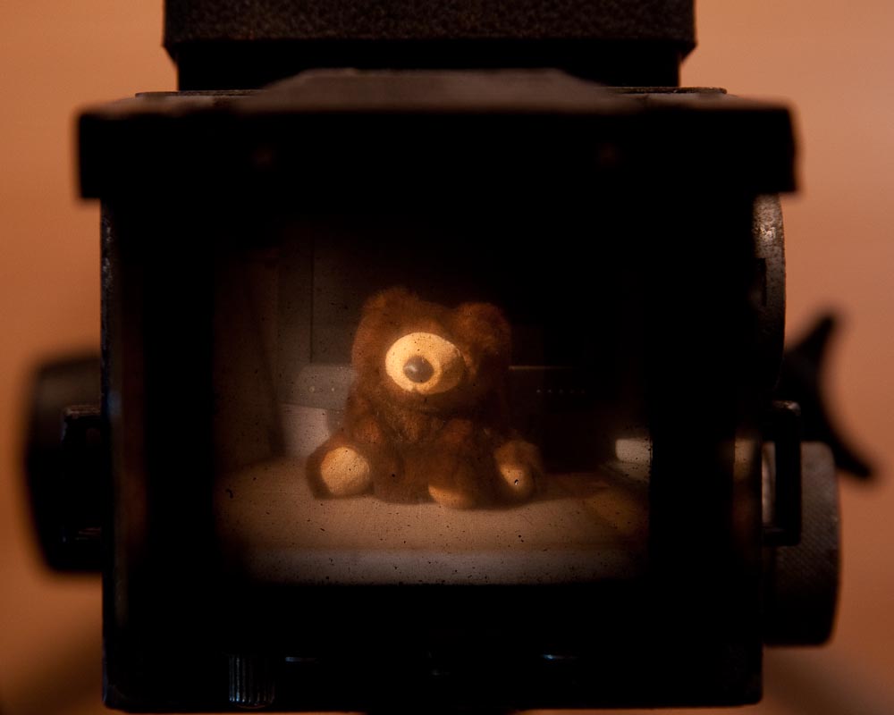
To illustrate the problems with a simple ground glass, the image to the right shows the view through an pre-war Ziess-Ikon Ikoflex. The illustration is a bit deceptive, as I actually ended up use a flash to illuminate the scene after focusing under as much light as I could get and guessing some. With out the flash the metered exposure for the screen was about 2 EV. The actual light levels metered at about 7 EV.
The easiest solution, if it could be called that, to the focusing problem is to simply not focus. In fact there have been several cameras made that used hyper-focal focusing (as many cameras in cell phones have done) in an attempt to get around the focusing problem. However hyper-focal focusing also remove the ability to use focus and depth of field to creative ends. It also be necessity limits the maximum focal length that can be used and fixes the aperture usually to something somewhat narrow and that limits the light the sensor can see.
The next easiest solution is to simply guess; well it’s an educated guess at least. That is, mark the lens at points that correspond to different distances and turn the lens to the distance that seems about right. This is one reason to have good distance scales on a lens, though there are others as a good distance scale can provide a lot of useful information. This technique is often referred to as zone focusing.
The two biggest problems with zone focusing are when used with fast lenses, lenses with long focal lengths or worse both. Fast lenses, necessary for selective focus and blurred backgrounds, have very shallow depths of field necessitating very accurate focusing. Long focal lengths too have very shallow depth of field, and require accuracy at quite great distances before the depth of field is large enough to matter. The combination of a fast long lens compounds the problems even more.
Clearly a better way is needed.
Finding the Range
Let me back track a second and talk about how you actually focus a lens. Lens’s bend light, and the amount they bend light we call the focal length. With an infinitely distant subject, a lens will focus light at a distance equal to it’s focal length. As the subject gets closer, the lens will focus focuses the light behind the infinity focal length, and so to focus we move the lens further away from the film or sensor.
The key here is that the distance you have to move the lens to refocus the image is proportional to distance from the lens to the subject. This typically expressed as s′-1 = f-1 + s-1 where s is the distance from the first principal point to the subject, s’ is the distance from the second principal point to the focus point, and f is the focal length.
More importantly though, this meas that the problem of focusing a lens can be changed from one looking at an image and trying to determine how sharp it is, to one of figuring out how far away the subject is and that directly tells us where to place the focusing elements in the lens.
In other words, what’s needed is a way to measure the distance to the subject with enough accuracy to allow for correct focusing. A tape measure would do, but probably isn’t going to work well for photography. Even if it did work, in many ways, it would only be marginally better than guessing with out a guide. Just imaging asking the important public figure you’ve been hired to photograph to hold one end of the tape measure while you setup the camera.
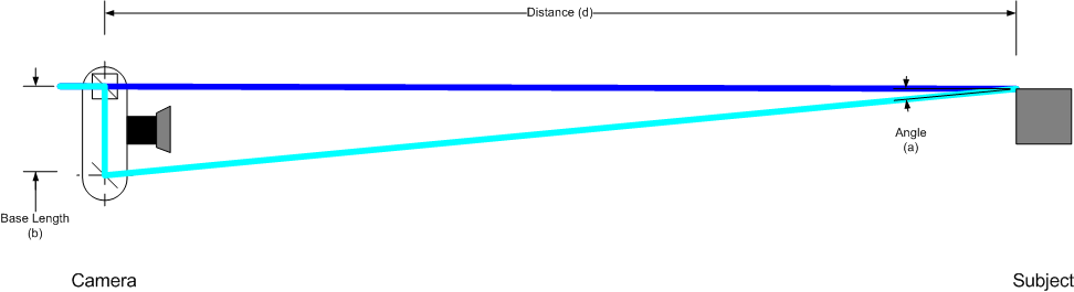
There is, however, another way to measure the distance to an object with out physically extending a measuring stick to the object. This works because of the trigonometric relationship between angles and the lengths of the sides of a triangle. It doesn’t take long to realize that using trigonometry as a base, the distance to the subject could be computer with out ever leaving the camera.

To make this trigonometric solution work you do need to know one thing ahead of time, the size of the subject. In addition to that you need a way to measure the angle of the subject and a formula to convert that into a distance. One approach, and what’s used in long distance rifle shooting, is to use a scale in an viewfinder or scope to measure the angle the subject covers from your position. The scale is marked at positions that correspond to known angles. Commonly, at least in rifle scopes, these marks are made in milliradians (mils) or minutes of angle (MOA).
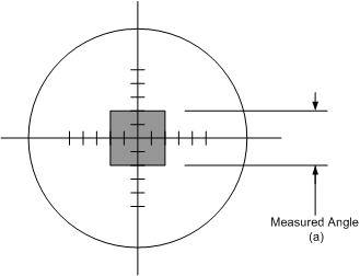
If the hypothetical reticle in figure above is marked using milliradians then the subject covers an angle of 4 mils; further if the subject is known to be 6″ tall. Solving d = 1 ÷ stan(α) for the values given, and a distance of 41.6 inches.
Whether or not this is more practical than a tape measure is probably up for debate, what isn’t debatable is that this still isn’t practical for photography. Accuracy is dependent on how well you know the size of the subject and how accurate you can measure the scale and the whole thing is predicated on being able to work out an equation on the scene as a table is still problematic because of the errors in subject size. Fortunately for people shooting rifles, an error of a foot or two in front or behind the target often has little impact on a shot that’s covering hundreds or thousands of feet. However, an 85mm f/1.4 lens used to make a portrait has a total depth of field of only 4.1 inches at 10 feet.
For what it’s worth, I’m not aware of this style of ranging ever being applied to common photographic equipment. It’s certainly not accessible to most people. However it does introduce the trigonometric strategy for calculating distance rather clearly and that’s what all focusing aids based on range finding use one way or another.
The Coincident Image Rangefinder
The solution to the having to solve equations is to cleverly build that into mechanics of the rangefinder and present it to the user in a simple, easy to understand manner. The basis for doing that is to turn the triangle around so that the length of the subject in the previous figure now becomes a fixed length inside the camera/rangefinder.
The ease of use problem is solved by presenting the user with a pair of superimposed images where adjusting the alignment of the images corresponds with setting the focus. This all comes together in a device known as a coincident image rangefinder (CIR).
In a coincident image rangefinder, the user knows they’ve found the correct distance because the two images in the viewfinder are perfectly aligned. Even better, because of the way the CIR works, the user knows (not that it’s strictly necessary in this case), which way the lens needs to be adjusted to focus the image.
Reversing the range finding triangle presents us with two solvable problems, measuring the angle and combining the two images.
The second problem is addressed by a beam splitter used as a beam combiner. A beam splitter, like most optical elements, it can be used in both directions. That is, when light is fed into two of the sides of the beam splitter, it will superimpose them over each other and send them out a third side.
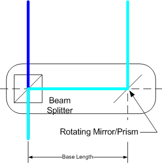
The second problem, measuring the angle formed between the two rays form the subject. This appears more challenging at first, however even that is relatively straight forward.
The law of reflection states that the angle of incidence is equal to the angle of reflection. From this two things become clear, first that when the mirror is rotated 45° as shown at right, the camera will be focused at infinity. Second, we know that the angle between the two light rays is equal to twice the angle the mirror will rotated.
From the second point, d = b × tan(2θ) can be derived; where d is the distance to the subject, b is the rangefinder’s base length and θ is the angle the mirror is rotated. Further, this makes measuring the angle α directly unnecessary to calculating the distance as it was done in the previous method.
The final piece of the puzzle is coupling the rotating mirror to the lens’s focusing ring, so the whole system can be driven by the operator simply by adjust the lens. The actual math is hidden from the user in this mechanical coupling.
How it all fits Together
When the lens isn’t focused properly, the reflected light from the mirror isn’t aimed at the center of the beam splitter. Thus the combined image is misaligned, the direction of the misalignment is also a queue to the direction of the focus error. The figure below shows an exaggerated schematic of a coincident image rangefinder at various focus positions.
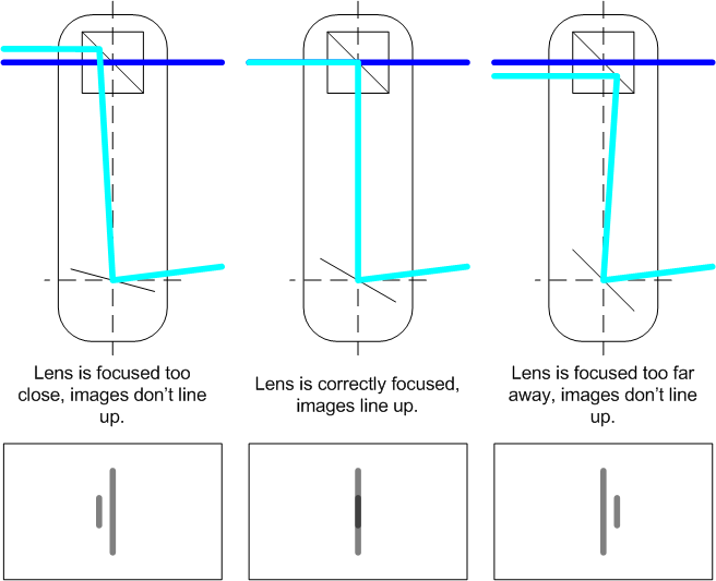
In practice it’s not quite this simple and there are more elements included to insure that both images are right side up and to project framing lines into the viewfinder, but the concept is the same for all coincident image rangefinders. Visual alignment is the key here, and what makes a CIR easily accessible to all users. The complicated math is handled by the people designing and building the cameras.
This system is used in cameras that are collectively called rangefinders. Arguably, the most successful example of this type of camera is Leica’s M series of rangefinder cameras.
Now that rangefinder provides an easy way to determine when the lens is focused it would seem like this should be the solution to all focusing needs. Simply stick a coincident image rangefinder on top of a camera and it’s good to go.
Not so fast…
Problems with a Coincident Image Rangefinder
There are a few issues the coincident image rangefinder presents. First since a rangefinder doesn’t work though the imaging lens, calibration of the lens-mirror link becomes very important. Small errors in mounting distance, lens construction or even rangefinder construction can throw the focus off enough to cause problems and they aren’t visible until after the image is made.
The second, and more fundamental, issue is accuracy. The rangefinder’s base length dictates the angle the mirror has to rotate for a given focus distance, because of that it controls the accuracy of the range finder. To make the measurement more accurate, a longer base length is needed to increase the angle the mirror has to rotate though. To give an idea how much rotation is involved, the mirror in a hypothetical rangefinder with a 60mm base length will rotate just over 0.5° from the infinity position when focusing on a subject 3M away; at 30m it will have been rotated just over 0.05°.
The objective for the rangefinder designer is to choose a rangefinder base length that is sufficiently long to provide enough accuracy with the focal lengths and working distances that will be used with the system. On the other hand the size of the camera places hard limits on the maximum length of the range finder base length. In turn the limits of the rangefinder place limits on the maximum focal length that the system can reasonably support.
This method of range finding works well, in practice, for wide-angle, normal and short-telephoto focal lengths because the depth of field at long distances grows quickly enough to mask errors in focus. However, telephoto and super telephoto focal lengths require much greater accuracy at long distances. That, coupled with the fixed external viewfinder makes long telephoto lenses unwieldy at best on this type of camera, and in general they aren’t available for rangefinder systems.
The coincident image rangefinder solves some of the problems of focusing a small format camera but not all of them. This is no slight of the design though. One things a rangefinder camera offers that was impossible to achieve, before digital at least, is a way to build a very compact camera that doesn’t have any large moving parts. In fact when the exposure is being made, the only moving part in a rangefinder camera is the shutter. This makes rangefinder cameras very quite, as well as eliminating mirror slap induced vibration reducing image quality.
The Split Prism: Flattening the Range Finder
Coincident image rangerfinders, and the rangefinder cameras that used them had their own problems unrelated to focusing. Composing through something other than the lens itself meant that the actual framing of the image was always approximate. Moreover, it made metering difficult at best and limited at worst, again, since the camera wasn’t metering through the lens. Moving to a single lens with a reflex mirror solved a lot of those problems, but brought the focusing problem back.
The split-prism focusing aid is something of a marvel of optics, and frankly just very cool. The optical principals behind the split-prism even live on as the core of phase-detect based auto focus systems. Besides the rather clever optics involved, the split prism also introduces a new way to think about focusing.
So far, the problem of focusing was a problem of finding the distance to the subject, even though the interaction may not seem so. This is largely a problem imposed by not being able to focus though the same lens that forms the image.
SLRs change the situation around considerably. The reflex mirror means you can position a focusing screen at exactly the same distance from the lens mount as the film, or now digital sensor is.
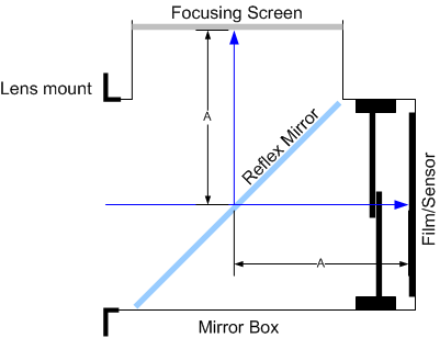
Thanks to the reflex mirror providing TTL focusing, the problem of making a focus aid is no longer one of building a device that measures distance. The problem is now one of building a device that provides the user with an easy to understand representation of when things are in focus.
Instead of starting with the split prism, I think it’s probably more useful to start with the human behind the camera.
Vernier Acuity
I want to start with a quick overview of vernier acuity. To quote from Modern Optical Engineering 4th Edition:
Vernier acuity is the ability of the eye to align to objects, such as two straight lines, a line and a cross hair, or a line between two parallel lines. In making settings of this type, the eye is extremely capable. In instrument design, it can be safely assumed that the average person can repeat vernier settings to better than 5 seconds of arc and the he or she will be accurate to about 10 seconds of arc. Exceptional individuals may do as well as 1 or 2 seconds. Thus the vernier acuity is 5 or 10 times the visual acuity.
With that definition in mind, the engineering objective should be obvious. If you can transform the focusing problem from one where the user has to judge when the image is maximally sharp (resolution) or has maximal contrast, into one where the user merely lines up a misaligned image there are numerous benefits. Not only do you dramatically improve the accuracy of placing focus, but you make nailing focus something that’s both far more accessible to photographers and you make a system that’s less demanding of the user under high pressure conditions.
Incidentally, the coincident image range finder also exploits vernier acuity in the alignment of image in the viewfinder.
So the trick to making a TTL focusing aid is to find something that can produce a lateral offset to an out of focus image, and do so without being significantly thick such that it can fit in the standard focusing screen.
Enter the prism.
The Prism
Prisms are probably best known for their ability to disperse white light into the rainbow of colors. The effect is called dispersion, and it’s a result of different wavelengths refracting at different angles when passing through a refractive material. As photographers we’re most accustom to this effect presenting chromatic aberrations in lenses that aren’t designed to correct and account for it.
However, dispersion isn’t what makes prisms useful for the split-prism rangefinder. The neat trick of prisms is that they bend light but don’t focus it. This is opposed to lenses, where they bend light but because of their shape light passing though different parts of the lens will bend towards or away from a focal point. With a prism, it doesn’t matter where the light hit the surface, the angle it bends is fixed.
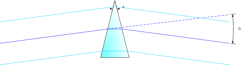
The above is something of an idealized diagram of a prism. The blue lines indicate the potential path of a light ray through the prism. So long as the rays are the same wavelength, the deviation angle (D) will always be the same regardless of where the ray intercepts the prism.
So why care that a prism bends light without focusing it?
This goes back to the problem of changing a contrast or resolution problem into a vernier one. More specifically, if we look at what that bend in the light does to what you see.
Putting the Prism to use as a Focusing Aid
With that basic understanding of what a prism does, we can now look at the split prism focusing aid in that light.
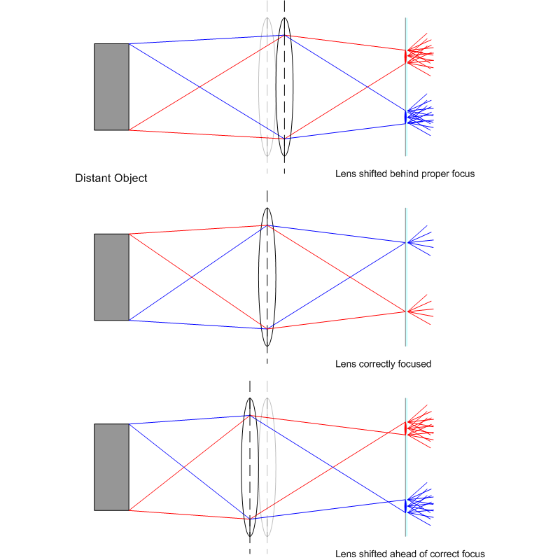
As photographers, we know that there are 3 general cases for which the “focus” of an image can be; in focus, front focused, and back focused. In the two out of focus cases, for our purposes how much out of focus isn’t especially relevant, the only thing that matters is where the light is being focused with respect to the ground glass or film plane.
Before I start with the ray diagrams, I want to make a note for those unfamiliar with ray tracing in optical design. A source emits light rays over all angles covered by the lens, for the sake of simplicity and clarity I’ve chosen exemplars (red and blue rays) from the extremes and omitted the rays that are passing through the center. In addition, I would point out there is no scale in these diagrams; they are meant to be illustrative and are exaggerated not precisely calculated; they are also simplified in how they show light passing through the optical elements.
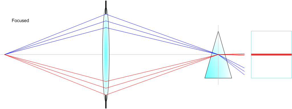
Let’s start with the focused case. With the lens properly focused, the lens is forming the image in the middle of the prism. The prism in turn bends the incident light directly back towards the eyepiece with effectively no offset.
It’s also important to note that the prism, unlike a ground glass, doesn’t use all the available light to render its image. The orientation and vertex angle of the prism, force the optical geometry in such a way that it only passes light form one side of the lens, and actually from only a part of that side (red rays). The rest of the light (blue rays) is dispersed in such a way that it doesn’t contribute to the formation of a visible image.
Moving on to the front focused example. In this case, the image is being formed in front of the desired plane of focus. However, because there is nothing to block the rays they will continue past where they’re focused and being diverging again, at least until they reach the prism.

The prism again bends the incident rays and sends them towards the eyepiece. However, because the incident rays are not hitting the prism centered the way they were in the previous example, the user looking though the eyepiece sees the virtual image formed by the prism offset from the center towards the vertex side of the prism.
The final case to consider is the case where the lens is focusing the image behind the film plane—the back focused case.
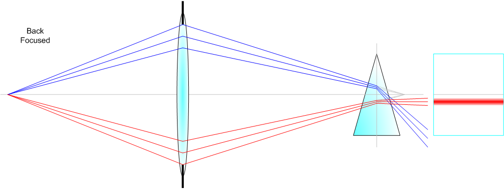
Like the previous out of focus case, the back focus case the lens is again forming an image somewhere other than on the plane where it should be. However, in this case the prism is intercepting the light before it is focused and bending it towards the eyepiece, resulting in the out of focus image appears to be offset to the base side of the prism.
One Prism or Two
Judging from the above diagrams, one might wonder why bother having two prisms. One prism will create an offset image, and as a result turn a contrast/resolution problem into one that relies on vernier acuity instead. The answer of course is simply that by offsetting in both directions the accuracy of the split prism is doubled. In other words, where a single prism might show a given focus errors as a .5mm displacement in the viewfinder, two opposed prisms will render will double the offset and render it as a 1mm lateral displacement.

Constraints
The first constraint on an actual split prism is the thickness and makeup (material and therefore index of refraction) that the prism can be made from. For example, a Canon EC focusing screen used in their EOS-1D bodies is only 1.5mm thick. Assuming the split prism is 7mm wide and tapers to an infinitely small point, the absolute maximum vertex angle is around 12°. In practice, of course it can’t taper to a point that small and therefore will be somewhat, or considerably less.
The second practical constraint is on the material, and therefore the index of refraction. If the split prism is molded into the focusing screen as part of the material, then it’s index of refraction will be confined to whatever that optical surface is.
As I’ve noted, the geometry of the prism dictates the angles though which it will actually pass light as a coherent image visible to the user. Combining the two above constraints on angle and material, the prism in turn dictates the maximum and minimum angles of incident light that it can render.
Further, because the f-number is defined as the ratio of aperture diameter to focal length, the geometry works out in such a way that all lenses of the same f-number will focus light with the same incident angles. Therefore, the performance of the split prism can be characterized in terms of a maximum aperture that it can turn into a usable image.
It would probably be an understatement to say that the split prism is fundamental to where photography is today. The same basic principles are used by the micro-prism collars, the traditional phase detect AF systems, and even new in-sensor phase detection systems.
Automatic Focusing
The idea of automating focusing has probably been around a long as cameras have been, but the dream of doing something and the technology to enable it, aren’t necessarily one and the same. In the late 70s and early 80s microprocessor technology had reached a point in terms of miniaturization, cost, computational power and overall complexity that it was possible to start really looking at autofocus as a serious technology that cameras could use.
External Range Finding
There was some early experimentation with using laser or ultrasonic range finding to focus cameras. However, the extent of that work was limited, as there are serious challenges that such a system has to overcome and doing so doesn’t work better than the alternatives.
From a technical standpoint, these kinds of solutions are just timing problems. Send a pulse of light, time how long it takes to get back to the camera, divide that by 2, and multiply by the speed of light and you have a distance. Sound works the same way, but being slower than light has less precise timing requirements. However, it’s also more susceptible to environmental interference.
In the end, these types of systems never saw much adoption as they aren’t necessarily accurate or reliable enough for photography. One of the biggest problems is you can’t actually use this type of system to focus on a specific part of the frame, though the lens. You can’t easily steer the rangefinder to point at the eagles eye the same way you can just put a TTL AF sensor over it.
That said, a ultrasonic rangefinders still show up occasionally as complementary or suppliemtary devices. For example, Red Rock Micro has brought a ultrasonic range finder to market as part of their Micro Remote focusing system, to provide real-time subject distance information as an aid to pulling focus.
Phase Detect AF
Phase detect AF is basically an extension on the concept exploited by the split prism focusing aid. Only remove the user’s eye and brain from the equation, and replace it with a pair of linear photo-diode arrays arranged in opposing directions. Like the split prism, the autofocus system is working towards aligning the “images” seen by the two AF sensor stripes.
Phase detect AF systems have 3 advantages. First, since it’s a TTL Focusing method not an external range finding method, it can be accurately placed on the subject without also being subject to environmental interference. Additionally, since it’s a TTL system, there are no parallax or alignment issues. What you point it at is what it will try and focus.
Second, it’s relatively computationally simple. This isn’t nearly as much of an issue today, as it was in the late 70s and early 80s when the first autofocus cameras were being developed. Phase detection requires neither a fast or precise timing system nor significant signal processing, it merely needs to compare 2 1 dimensional arrays for equivalence, a process that can be done very quickly, even with early 80s era micro controllers.
Finally, phase detection provides the autofocus system with context beyond just whether or not the subject is in focus.
While computers are adept at processing inputs, they generally don’t have a way to contextualize those inputs unless the inputs provide that information inherently. Because the split prism shifts the images differently depending on whether the lens is front or back focused, the autofocus system can use the direction of the misalignment to determine whether it’s starting front or back focused, and in turn drive the lens towards focus form the start instead of having to hunt.
However, like the split prism focusing aid, phase detect AF has its limitations. The geometry of the optical system places limits on the lens’s maximum aperture. Slow lenses may not even register on the AF sensors, and fast lenses make small displacements will be less accurate on a sensor designed for a slow lens. These limits are often addressed by using multiple sensor arrays and various alterations to the optics in front of them, such that many modern phase detection systems have multiple sensors for each AF point that are employed to maximize accuracy and operating range.
As computational power has increased, phase detect systems have begun integrating information from more points; from the metering system, and even distance data reported from the lens. In their current iterations, phase detect AF systems can integrate data from many 10s of distinct points, each of which can have as many as 6 or 8 AF stripes, with each stripe having 10s or 100s of pixels recording data. Further, they can process all of that information to drive fast AF lenses across their whole range of focus in just 10s of milliseconds.
Contrast Detection AF
Increasing computational power in the 90s, and especially going into the 2000s has made contrast detection increasingly practical as a means of autofocus. Contrast detection AF exploits the inherent increase in contrast as an image is focused.
There are a number of ways to process the image data into usable information for contrast detection AF; all of which are suitably complicated enough discussions on signal processing that I don’t even want to try and describe them. That said, with modern digital signal processors contrast based AF can be fast, fast enough to even be competitive with phase detection systems.
However, contrast detection isn’t without its pitfalls. Namely, contrast detection relies on there being sufficient contrast to process into usable focus. Low contrast scenarios, like low light, may result contrast detection systems having to take longer to collect and process information.
Moreover, we’re all familiar with the effect increasing ISOs have on image noise. In a phase detection AF system, the photo sites are unencumbered with efficiency squashing requirements like a low-pass and color filters. Further, the phase detect sensor’s “pixels” can be sized independently of the sensor pixels to perform sufficiently well in the low light conditions without having excessive noise or integration times.
However, since contrast detect systems typically use the imaging sensor as sensor gain has to be increased to maintain sufficiently short integration times for the real time EVF to work, the AF algorithms have to contend with increased noise in the signal. Though there are ways to combat that, it takes increased processing power and time.
One final consideration is what I’ve been calling context; the ability for the camera to discern something about which direction it needs to drive the lens to drive the image towards being in focus. Contrast detect systems do not provide the camera with that kind of information like a phase detection system does. As a result, contrast base systems always start by “hunting”. That is they have to take a contrast measurement, move the lens, take another measurement, and compare them. If the contrast improved then the lens is being driven in the right direction, if it got worse, then the camera has to reverse the direction the lens is driven basically start over.
A similar situation actually exists at the end of the focusing process as well. Since the contrast detection algorithm can’t actually determine that it’s reached the point of maximum contrast, or at least that continuing would result in lower contrast, it has to overshoot that point, measure the drop in contrast, and back up to the maximum point.
None of these issues are fatal to contrast detect AF. In fact, for still photography as long as the minimum speed is fast enough, they aren’t even real considerations. However, they do raise their ugly head if you’re shooting video on a VDSLR or mirrorless and the camera is set to autofocus, simply because all that hunting and over shooting can show up as obvious focus movements in the video and they are distracting.
On the other hand, contrast detection systems have a few nice advantages over phase detection systems.
First, there is no maximum aperture requirement. If the lens can form an image on the sensor and there’s still sufficient light, the camera can focus it. Cameras with phase detect AF limits, like Canon’s 50D, or 7D (limited to lenses f/5.6 or faster) in live view contrast based focus mode can focus with any lens or lens and teleconverter combination, regardless of what the aperture actually is.
Secondly, there are fewer mechanical parts. Pure contrast detect cameras have no need for a reflex mirror, or the optical path for the phase detect sensor separate from the main sensor. The increased complexity in a contrast detect system comes in the initial costs of R&D developing the algorithm, not in the unit costs of building the camera.
Finally, because the contrast-based system is doing the focusing using the actual imaging surface, there’s no change for error being introduced from misalignment or externalities. With the exception of viewing an image on a ground glass, all of the other focusing systems require precise alignment at some point in the system. That’s not the case with a contrast-based system using the main image sensor.
Hybrid Systems
Recently a number of companies, Canon and Nikon being the biggest, have started employ hybrid systems that embed phase detection “pixels” into the imaging sensor. The idea is that it should speed up contrast detection and provide a better focusing experience when shooting video.
In the hybrid system, the phase-detection points work to provide the camera with the context as to whether the lens is currently front or back focused. This eliminates the initial hunt, which in turn speeds up the AF process slightly as well as removing one of the potential distracting hunts form videos.
The system then uses the phase information to make gross focus adjustments to close rapidly on achieving focus without having the computation overhead of measuring contrast at each of these steps. Finally, when the phase system has put the camera close to being in focus, the camera can take over with contrast detection to make the final focus placement. If the lens’s aperture isn’t sufficient for the phase points to work, the camera simply falls back on contrast detection for the entire operation.
That’s the theory at least. In practice, there’s still a lot of variability in performance based on AF algorithms.
Nikon was the first to release a camera using a hybrid system, and it’s the core of the AF system in their Nikon 1 series. Canon followed suit, at first with the simple hybrid system in the T4i and EOS-M. This system uses discrete phase detection pixels embedded in the imaging sensor similar to Nikon’s system. Then with a more advanced dual-pixel system, used by the EOS 70D, which turns virtually all the sensor’s pixels into pixels capable of measuring phase differences as well as recoding image data.
In many ways, hybrid systems are the best of all worlds, and have few if any of the drawbacks of their counterparts. Unlike pure phase systems, hybrid systems don’t have the increased complexity of mirrors and optical alignment; nor do they suffer from aperture limits. Moreover, unlike pure contrast systems, they have the additional context of knowing which way to drive the lens towards focus from the outset, and have the ability to do so, at least in some cases, with much lower computational demands allowing spare CPU time for other processor, or better yet lowering the overall power consumption.
What Goes Around, Comes Around
In many ways, the history of focusing techniques has been cyclical. We started with a loupe on the ground glass, manually judging the contrast and sharpness of the image, and adjusting the camera accordingly. As cameras became smaller, we developed aids to assist us in judging focus that weren’t as sensitive to our own limitations. These advances ultimately culminated in the split-prism focusing aid, which reduced a complicated problem to one virtually anybody could do accurately and repeatedly.
The desire to broaden the capabilities and usability of cameras had in turn pushed designers to autofocus systems. Technical limitations pushed those early developments towards systems that were based in principal on the split prism. As processing power progressed, and those technical limitations have removed, we’ve found ourselves developing autofocus systems that largely turn back to the original strategy of inspecting the image at the plane of focus and adjusting the lens. Sure the computers in contrast and hybrid phase/contrast autofocus systems can do that much faster and more accurately than human can, and hybrid systems provide the computer with much of the same contextual information that the photographer would have had simply by being there at the time.
Comments
Interesting presentation,congratulations!
Somme information about AF you can find in:
http:\/\/www.osim.ro/publicatii/rrpi/rrpi_2013/cuprins.pdf [Admin: Site’s content seems to have changed since origional posting, I’ve deactivated link.]
i regret, but the paper referring to AF history is in Romanian language. If you are interested I can sand by mail an English translation.
Best regards,
Octavian
What’s with this Latex? I can’t read those equations on my screen.
Sorry, at some point the latex conversion plugin must have gotten deactivated. Should be fixed now. Thanks.
Great article, good look at the history of photography focusing methods.
Corrections in CAPS to second last contrast focus paragraph:
“Secondly, there are fewer mechanical parts. Pure CONTRAST detect cameras have no need for a reflex mirror, or the optical path for the phase detect sensor separate from the main sensor. The increased complexity in a CONTRAST detect system comes in the initial costs of R&D developing the algorithm, not in the unit costs of building the camera.”
Hi brad,
Thanks for the corrections there.
Not mentioned is focussing by the film plane, this was used in the Ensign Commando camera and in the Mamiya Six camera.
As best as I can tell, the Ensign Command and Mamiya Six are just coincident rangefinders, which are discussed. Though I didn’t consider the fact that the rangefinder would be coupled to film plane instead of the lens. Fair point, thanks for pointing that out.