DIY Autofocus Calibration Target
As much as I swore off AF testing and calibrating, I’m back at it again. This time I’ve decided to forgo the sheet paper targets and build a target similar to the Lens Align. Now obviously, if you don’t want to spend the time building a target, a Lens Align is, to my knowledge, the best commercially available AF adjustment product and the Lens Align Mark 2 is very reasonably priced at about $80.
I had considered jumping straight into a how to article focusing on building the target. However, I’m not because I think it’s important to understand the considerations involved and how the limitations of your materials and construction accuracy affect the accuracy of the testing. Even if you choose not to build your own AF target, or wish to continue using a simple paper one, the thought expiration can be illuminating.
Ultimately before I get to actually showing how to build the target, I would like to provide the tools so that anyone following along can design and build their own target with the confidence that it will be accurate enough to adjust their camera with their lenses.
Before building a prototype, I feel it’s necessary to assess the feasibility of designing an AF target with suitable accuracy to be useful, and that’s what we’ll be doing in this article. We do this by examining how autofocus micro adjusts work to determining the maximum error that can exist in the alignment and flatness of the target surface.
Feasibility Study
Understanding AF Micro Adjust Step Size
Auto focus adjustments are made in fractional amounts of the lens’s depth of field. This is necessary, as an absolute unit would only apply at a single distance. Adjusting the lens’s focus point back 1 foot may work fine when photographing a subject 20 feet away, but it would result in severe errors at say 2 feet away.
According to this Canon paper, an AF micro adjust are made in 1/8th depth of field steps. Though the document is specific to the EOS-1D and EOS-1Ds, it’s a fair bet to assume that it applies to all other Canon bodies, and likely to the bodies of any other manufacturer as well though I’ve yet to find published documentation on that.

Consideration is given only to the step size, since there’s no need, or ability, to be more accurate than the step size. Even if the target is designed to handle and measure autofocus errors at much higher precision, the camera can’t correct that accurately. Thus the step size, determines the worst allowable error margin.
Targeted Testing Distance
Since depth of field is dependent on distance, the next consideration is a minimum distance to design the target to be sufficiently accurate. However, since the depth of field narrows as the distance decreases, and thus the required accuracy increases, reducing said distance too much immediately results in an impractical limitation for a home design.
With that in mind, I’m going to shift consideration from the min test distance to the actual test distance for a moment. The officially recommended test distance from all manufactures is the standard subject distance. For some areas of photography this is likely easy to deal with. Most portraits will be shot at a similar distances using a given lens. However, for many photographers, the subject distance will vary greatly resulting in the need to test at a distance that is effective but not strictly equal to any actual subject distance.
This is somewhat more problematic, since I can find little published by the manufacturers to give a hard number. In a previous article, I claimed that Canon recommended testing at distances at least 50 times the focal length[i]. Unfortunately, I’m no longer able to find a Canon source for that, though that number is noted repeatedly around the web. Alternatively, Lens Align suggests a minimum of 20 times the focal length[ii].
Targeted Aperture
In addition to distance, the aperture controls the size of the depth of field. Wider aperture resulting in shallower depth of field also put increased demands on accurate construction. Though one certainly can target any aperture they desire, I see little sense in targeting an aperture value that you’ll likely never own or use, at least in the near future.
Calculations
For my target, I elected to use a design distance of 25x the focal length, with the expectation that I’ll be testing at 50x the focal length. I also elected to calculate the 1/8th DoF values for a verity of apertures and deiced after looking at the numbers what I thought was a reasonable limit.
I did the calculations in bulk using MS Excel. Though they can be done equally well with a depth of field calculator. In fact, I’ve modified my depth of field calculator to include a shortcut for jumping to a multiple of the focal length and the 1/8th DoF values.
The Table below summarizes some common apertures for Canon’s 3 sensor sizes, Nikon’s DX format, and 4/3rds at a distance of 25x the focal length.
| 1/8th DoF size in inches | |||||
| Max Aperture | Full Frame | APS-H (1.3x) | DX (1.5x) | APS-C (1.6x) | 4/3rds (2x) |
| f/1.2 | 0.230 | 0.176 | 0.153 | 0.146 | 0.115 |
| f/1.4 | 0.268 | 0.206 | 0.179 | 0.170 | 0.134 |
| f/1.8 | 0.344 | 0.264 | 0.230 | 0.218 | 0.172 |
| f/2.8 | 0.382 | 0.293 | 0.255 | 0.242 | 0.192 |
| f/3.5 | 0.535 | 0.410 | 0.357 | 0.339 | 0.268 |
| f/4 | 0.763 | 0.586 | 0.509 | 0.484 | 0.382 |
| f/5.6 | 1.069 | 0.819 | 0.713 | 0.677 | 0.535 |
Feasibility Study Conclusions
The above table shows that for an actual testing distance of 50x the focal length (designed for 25x the focal length), the worst-case scenario, a 4/3rds camera with an f/1.2 lens, the test target can vary no more than about 1/8 of an inch.
For most materials that are easy to work with at home, that’s not an overly onerous requirement. It’s certainly possible to insure accuracy to a 1/16th of an inch with careful cutting and measuring.
I feel based on this feasibility study, that it is within the realm of possibility to construct a sufficiently precise autofocus test target at home.
Calculating the Camera Alignment Errors
The Alignment Problem
Alignment is an important, if not the most important, part in any autofocus test system. The real question is how much room for error actually exists.
As a point of note, in this article I assume an ideal target and ignore any errors in target flatness or construction.
While the last part focused on the errors in flatness and construction, this article focuses on the alignment errors caused by not having the camera perfectly centered on the target. The standard case is show below, where the camera is pointed at some angle other than completely straight at the target.

The first requirement to determining how large that misalignment can be is to determine how far the target can be rotated before the error in scale placement is high enough to affect the measurement.
The drawing below illustrates this error and shows the distances that need to be considered. The error from the target plane is given by the dimension E, this is the same as the “error margin” computed previously. When the error is shifted by a distance Doffset from the target centerline to the scale’s centerline the resulting angle (α) can be calculated.

AF Target Size
Before I calculate the angle α, a reasonable estimate for Doffset is necessary. While a detailed investigation of AF sensor coverage is certainly possible, a rough calculation is sufficient for this discussion.
The longest side of an EOS-1D’s AF box to be about 0.924°[3]. Since the AF point can cover more than the viewfinder displays, it’s desirable for the target to be larger as well. The question of how much boundary area allowed is certainly an open discussion, though I’m assuming 100% just for safety.
If the AF point dimension from the EOS-1D is used, at the focus testing distance of 15.5-feet for a 70mm lens, 3-inches at the focus distance is covered by the AF box. Allowing for a 100% larger sensor area, the target would need to be 6-inches on a side.
If the target is 6-inches and a reasonable scale of 2-inches in width is added then Doffset, from target center to scale center 4-inches. My prototype target uses an 8×8 inch target (printed as an 8×10 and cut down), with a 2-inch ruler, resulting in a 5-inch Doffset.
Note: I’m using the center of the sale in these calculations; you could actually use any part of the scale, the edge farthest from the center of the AF target being more constraining as it would reduce α slightly. I’m going to talk more about scale design in a future part.
Calculating α
The angle α is calculated using the following equation.
![]()
For the small (6-inch) target described above, α is equal to 1.647°. For the larger target I used in my prototype, α is 1.318°. The larger α is the more room to misalign the camera before affecting the results.
Implications of α
The implication of the angle α comes from the geometry of the target with respect to the camera. As the drawing below shows, geometry dictates that α is not only the angle the target forms, but also the allowable angle away from the true that the camera can be placed in without affecting the accuracy of the test.

Knowing the maximum α can be, and that it also represents the angular error at the camera it’s possible to calculate a linear error at any given distance. That is how far away from the imaginary perfect position the camera can be at the testing distance. You can imagine this as a cone projecting out from the center of the AF target. As the distance away from the target increases, the area where the camera can be without affecting the results does as well.
For example, if a 50mm f/1.2 lens on a 4/3rds camera is tested at the minimum recommended test distance[4] of 98.4-inches; with a 4-inch Doffset or α = 1.647°, the allowable linear error at the test position, Ecamera, is 2.81-inches.
This is actually quite a large error margin. It’s certainly big enough that alignment could be done with a tape measure finding the approximate center of the lens relative to the floor and a wall, and placing the center of the target at the same approximate location.
Aligning the Camera
The actual alignment of the camera and target is certainly one of the major considerations, if not in the accuracy of the test, at least in how easy it is to setup for the testing.
One strategy is simply to do what I suggested in the previous article and use a tape measure to position the target in the necessary spot. It works, and can be accurate enough to get everything close enough to make for accurate measurements. However, it doesn’t make an easy quick way to setup the sight.
To do that there needs to be a sighting system of some sort. There are several ways to approach the sighting problem, but before I look at them, accuracy and depth of field must be considered.
Accuracy and Inaccuracy as Imposed by Depth of Field

Most simple sighting systems work by aligning two or more sight points. When the sight points are aligned, the camera is aligned with the target. This strategy requires placing at least one of the “sights” either in front of, or behind, the other.
Accuracy is dependent on the distance between the two sight points, the longer the distance the more accurate the alignment can be. However, this presents a problem in this application, due to depth of field.
One way to simplify the target design and construction is to use the target itself as one of the sight points, with the second sight point either in front of or behind it. As a result, the useable depth of field is in turn halved.
The question ultimately is how far from the target can the second sight point be before it’s unusably blurred.
Fortunately, several factors allow the design to be simplified further. First, we can do the sighting at an aperture narrower than the lens’s wide-open aperture. In fact, due to the way modern SLR viewfinders are designed, at least in part, sighting thought he viewfinder will act as if the lens was stopped down to f/4 or f/5.6.
Further simplifying things, is that testing is typically conducted at a multiple of the focal length—it doesn’t necessarily need to be 50x either, as long as the multiplier is held constant. This reduces the depth of field calculations to being dependent on just the aperture. In other words, all f/2.8 lenses will have the same depth of field at the test distance regardless of their focal length.
Using both simplifications it’s possible to calculate how far away from the target the second sight point can be.
Calculating the Limits Imposed by Depth of Field
The easiest way to compute the placement of the second target point is work the depth of field process in object space (where things are) as opposed to image space (at the sensor) like it’s usually done.
For this, I use an equation presented by Harold Merklinger, in his book The Ins and Outs of Focus. This is based on the geometry of the scene and nothing else. Moreover, I make a simplifying assumption that the distance from the lens to the subject is equal to the distance from the film plane to the subject. In reality they are slightly different (<10% at the 50x testing distance) but close enough that it doesn’t introduce enough error while greatly simplifying finding the center of the lens.
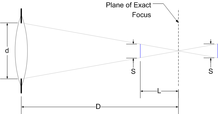
The formula used is show below. S is the spot size, L is the distance in front of behind the place of exact focus, D is the distance from the lens, and ‘d’ is the aperture diameter.
![]()
Further applying the simplifying assumption discussed above, that the testing distance is always a multiple of the focal length—in this case, 50—the formula can be simplified as show below.
![]()
Where N is the aperture of the lens as express by the f-number and L is the same as above.
S is simply spot size where the target is unusably blurred. In practice, this works out to be twice the width of the target itself. Using this equation, we can solve the practical maximum sight point distance for any given aperture when the target is 50-times the focal length away from the camera.
Additionally the simplifying assumption based on viewfinder accuracy can be applied here to simplifying things further (reducing N to either 4 or 5.6).
For example, if an Xacto #11 knife blade was used as the front target point, S is 0.04 inches (0.5mm). Using f/4 as the sight aperture, and 50x the focal length as the testing distance, L, the upper limit for the front point is 8 inches.
Thinking about the Design
Knowing the limits is one thing, designing the target is another. If we stop and take a moment to look at the commercial Lens Align products, their sighting system utilizes a hole in the center of target board and a rear placed sight post. This is certainly guaranteed to have you pointing at the center of the target when it’s properly aligned, but it increases the complexity of a DiY solution.
One possible simplification is restricting the number of degrees of freedom the target has to deal with.
The sighting system serves to align things in 3D space where there are 6 degrees of freedom in which the camera needs to be orientated. However, if you begin to constrain those degrees of freedom the alignment problem becomes simpler.
For example, constraining the camera and target somehow would seriously constrain the number of angles that need to be dealt with. One such way is to insure the camera and target are level and that the center of the lens is at the same height as the center of the target. Doing this reduces the problem to a single angular error (yaw) which can be dealt with by a single vertical sight.
The problem of insuring alignment still exists, to some degree however, as I showed in the last section there’s a fairly large amount of room for error in placing the camera.
Another simplification is that the alignment points need not be placed in the center of the target. Removing that constraint removes the difficulty of placing an opening that has to be closed in middle of the alignment surface. Actually, this can be dealt with by having the target itself slide into the “holder” covering the alignment sight.
Fortunately, it’s not necessary to have the alignment marks in the center of the target. Perspective that even off center alignment marks will become centered when the target is aligned. In other words, a set of pins or other sighting marks can be placed around the target such that the line up with marks on the target instead of being centered.
The key consideration here is insuring that the center of the target is clear of things that could throw off the autofocus system.
In my prototype, I used both simplifications I just noted. My alignment pin is a hobby knife blade stuck in the front of the base plate about 6” in front of the target, well inside the DoF limits for an f/4 lens at the 50x test distance. Additionally, I only use a single sight point to align the yaw of the target relative to the camera, relying on both leveling the target and camera, and setting the camera so the lens is centered at the same height as the target.

Designing the Target
While the target’s construction tolerances are important, if there is nothing to focus on and no scale to read, none of that matters. The non-obvious part is that how the target is designed can seriously affect how the auto focus system performs.
A brief overview of Auto Focus
If you’ve ever used a manual focus camera with a split prism screen, you’re already familiar with the way autofocus works, even if you don’t realize it.
The exact details are somewhat outside the scope of this article, but at a simplified level, autofocus works something like this:
Light from the lens is split and sent though a pair of prisms, the prisms converts focus errors into laterally shifted images. The shifted images are projected on to a pair of linear photo-sensors—think of this as a single row of pixels from the camera’s main sensor. The camera then looks for patterns on these sensors and then tells the lens to focus so that the sensors both show the same pattern.

The diagram attempts to illustrate the “AF system’s” view of a high contrast low frequency target, i.e. a black line on a white background. The rows of boxes above and below the images represent the AF sensor’s photo sites, and are colored to represent what the sensor would output. This is the simplest best-case scenario for an AF system, and it’s very easy for the camera to deal with.
The ultimate design objective is to make sure that the above simple scenario is the only scenario that the camera can experience across a wide range of conditions.
Potential Design Issues
The design of the autofocus sensor poses 3 broad problems, alignment, contrast, and image confusion.
Alignment
The linear nature of the sensor means that its ability to detect “lines” is directional. Moreover, if the line and sensor are aligned, in other words a vertical line and a vertically oriented sensor, the sensor will be unable to find anything to focus on at all.
Fortunately modern AF system design has reduced the severity of this problem with the wide spread use of “cross-type” AF points. These AF points place two sets of linear sensors at right angles to each other. This eliminates the possibility of having the subject and sensor aligned in such a way that focus cannot be achieved. What is perfectly aligned to not work with one sensor pair, will be in perfect alignment with the second pair.
From the AF target design perspective, it’s simple enough to insure that the target is functional regardless of sensor orientation and availability of cross type sensors, that it’s ultimately pointless to worry too much about the sensor type. Instead, a target pattern consisting of lines crossing at 90° angles is sufficient to cover the possible alignment cases.
Contrast
Due to their design and the requirements they must operate under, autofocus sensors tend to be significantly less sensitive to contrast than the actual imaging sensor. The simple, and obvious, solution to this is to insure the autofocus target has the highest possible contrast. To that end, it should be printed using fully saturated black on white paper.
Resolution/Image Confusion
The ultimate design objective is to insure that the target cannot “confuse” the camera’s autofocus system. Insuring high contrast and coverage is one thing, but going overboard with providing a target field can lead to accuracy and repeatability issues.
The mechanism is simple. When there is a high frequency pattern (like repeating lines), it’s possible for the defocused image align in such a way that the autofocus system things that focus has been achieved when it hasn’t. The image below shows this condition occurring in a split prism on a manual focus camera.

Of course, in a manual focus system we know that focus hasn’t been achieved, but such “outside” observations are not available to the computer in the camera. However, to the auto focus system, all it can “see” is what’s in the inner most circle. As far as the AF system knows, this could be an in focus image of a “soft” set of parallel lines, not the out of focus image of a set of lines. Though, it’s worth pointing out that SLR AF systems are more accurate than this simple demonstration implies.
This too has a simple solution; don’t use repeating patterns in the target design.
Sound Target Designs
If there’s anything that should be obvious about designing an AF target, it’s KISS (keep it simple stupid). What you clearly don’t want it something fancy that could ultimately lead to inaccurate focus. As such there are two target designs I tend to favor. The first is a simple pair of wide lines crossing at right angles running horizontally and vertically across the target.

The second is alternating quadrants of black and white.

Both of these targets are high contrast, suitable for both vertical and horizontal autofocus points, and have no high frequency patterns that could accidentally induce error.
Building the Target
Once you understand the considerations that go into designing an autofocus adjustment target, the actual process of building the target is comparatively trivial. The principal consideration is simply to insure the target is flat enough to meet the requirements imposed by the first part and rigid enough to not flex appreciably.
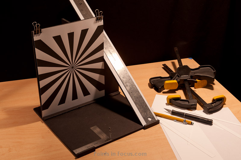
I built my target form 3/16-inch foam core board. The biggest consideration was to insure that the sheet was flat and smooth prior to cutting. While you could certainly force a bowed sheet to be flat and stable, it’s considerably easier to work with a flat sheet from the get go.
The bulk of my design is pretty obvious from the image. There is a singe 1″ wide piece glued to the back of the vertical target to provide stiffness. The overall dimensions of the target are 8×10″, the ruler is 2″ wide, making the entire foot print about 10 by 10 by a little less than 18″ for the ruler.
The key to this undertaking is understanding the design considerations and the math involved in computing the allowable tolerances as those are what define how precise you must be with your work. After you’ve got a handle on the required tolerances and principals, the design and construction of a working target is relatively simple.
While I can certainly understand the desire to save the time and effort by buying commercially available AF adjustment targets, for the photographer on a budget it’s perfectly workable to build your own with readily available tools and materials and achieve a sufficiently high enough level of precision to have a useful result.
- http://www.pointsinfocus.com/2010/01/auto-focus-micro-adjustments-using-live-view/
- http://www.whibalhost.com/lensalign/what-is-lensalign.html
- A 70mm lens focal length, aimed at a ruler. The box subtended approximately 1/2” on the ruler with the camera placed 31 inches from the ruler.
- 50x the focal length (see previous article).
Comments